www.iFourWinns.com

Dedicated to Current and Future Owners
It is currently Fri Apr 26, 2024 7:56 am

All times are UTC - 6 hours [ DST ]


Post new topic Reply to topic  [ 9 posts ] 
Author Message
PostPosted: Thu Mar 29, 2012 11:05 pm 
Offline
Dolphin
User avatar

Joined: Fri Jun 19, 2009 1:55 am
Posts: 83
Location: Desert Hills AZ
I've finally dived into the bilge and checked out the pump and the float switch, Last time I had the boat out the pump and switch gave me some trouble and it was kind of jerry-rigged and I was able to clear and test the pump and switch and it went back together and was working... So I was just revisiting it this week and nothing works so I tested the float switch and decided it was bad so I ordered a new one. Then I tested the pump and it needed a little prodding to get it running and without the hose connected it was moving the water I had put in the bilge. I hooked it back to the hose/tube and powered up but it didn't push any of the water out. I'll check the hose for blockage but I think the pump will get replaced regardless.

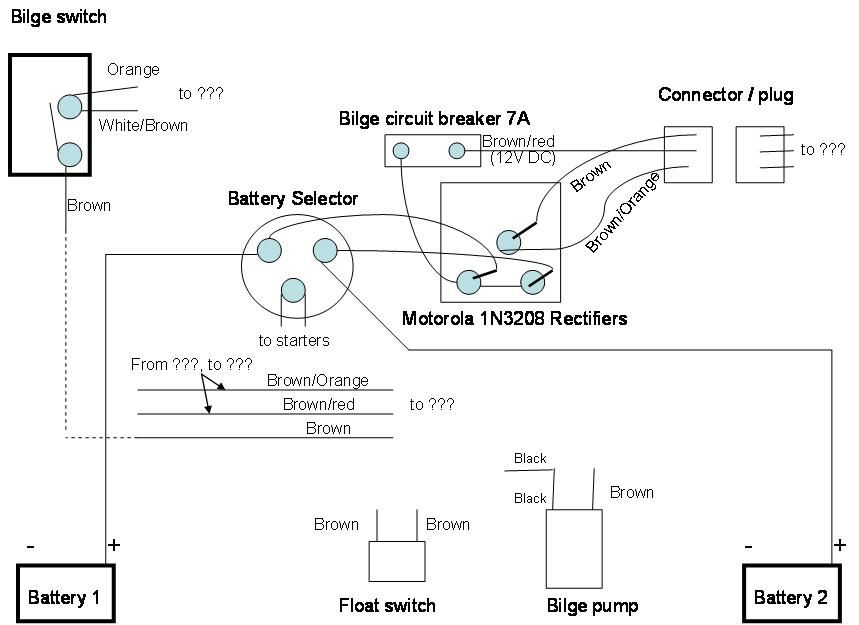
Now for the question(s). I'm not sure the wiring (for this circuit) was correct when I got the boat. I can't figure out how to get the bilge pump to run using the aft pump switch at the helm (right terminology I hope). I looked at the bilge rocker switch and I saw a BROWN wire, and when I tested the switch it made a contact through to the terminal with a White/Brown-stripe wire and an Orange wire (see diagram). The White/Brown wire and the Orange wire doesn't seem to run into the bilge area. And, the BROWN wire runs to the bilge...but I'm not sure where to connect it, or where to connect the Brown/red and brown/orange wires that are in the bilge ciruit (in the bilge area)

I've looked at diagrams from FourWinns but they do not seem to match what I'm seeing... can anyone help me connect the wires in my diagram?
Image

_________________
1988 Four Winns 261 Liberator Twin 460s


Top
 Profile  
 
PostPosted: Fri Mar 30, 2012 8:35 am 
Offline
email admin your custom rank

Joined: Wed Jun 01, 2011 10:21 am
Posts: 5667
Location: Austin, TX
I have no idea what you have.. but this is the setup in my 2000 h180
Image

_________________
1981 Columbia 8.7
2015 Yamaha FZR - 87mph - sold
2006 Yamaha GP1300R - sold
2003 Chaparral 215 SSI - sold
2009 Stingray 195CS - sold
2000 Four Winns H180 - sold
1976 O'day Daysailer II - sold

Rick's Four Winns H180 Mods/Upgrade Thread


Top
 Profile  
 
PostPosted: Fri Mar 30, 2012 9:56 am 
Offline
email admin your custom rank

Joined: Sun Nov 21, 2010 8:03 am
Posts: 2238
Location: Winthrop, Ma.
Keep it simple.

Go back to the float & pump. In total, going to both should be 3 wires in all. One is ground (NEG-), one (pos+) but ALWAYS on & the other (pos+) BUT controlled from the helm switch. The ground wire should be black, the other 2 are brown and I think brown & white, off the top of my head. Take a meter, to find the one from the helm. If the meter show 12V only when you flip the switch, you found it.

Is also sound like you need a new pump & float. The easiest thing to do, is buy a automatic pump that had the float in it. It should come with 3 wires as I mentioned before. Just fellow the instructions that comes with it. It should tell you which is ground or NEG, which to go to a switch & the other for constant 12v.

You can install a float & non-automatic pump, but it means more connections.

Its a 3 wire hook up, its not that bad. Just make sure you test it!


Top
 Profile  
 
PostPosted: Fri Mar 30, 2012 11:11 am 
Offline
Dolphin
User avatar

Joined: Fri Jun 19, 2009 1:55 am
Posts: 83
Location: Desert Hills AZ
Thanks Ric, for the drawing. That is really what I am trying to accomplish - it's just that my boat's wiring harness seems to introduce a few wires (colors) that I can't directly relate to the rocker switch without doing more digging, and the FourWinns diragram doesn't show the transition from a brown wire on the rocker switch to the brown/red and brown/orange wires it shows in the diagram. I have a few ideas I'm going to check out today, see my edited drawing. One thing I have to check still, is whether my automatic switch is always going to have power even if the battery selector switch is OFF, the way I am showing the circuit (I'm pretty sure it does but there is also small red wire attached to battery 1 positive terminal and I thought that was for the constant power to the automatic switch - I'll trace that out too.

I just read your reply Paul I., and I appreciate the help! I am going to spend some more time metering out the rocker wiring.

Image

_________________
1988 Four Winns 261 Liberator Twin 460s


Top
 Profile  
 
PostPosted: Fri Mar 30, 2012 1:50 pm 
Offline
email admin your custom rank

Joined: Sun Nov 21, 2010 8:03 am
Posts: 2238
Location: Winthrop, Ma.
What I like to do with any new boat I get, is to add a 2nd pump. Wire it to the 2nd battery also. So you would have 2 pumps working off of different batteries. It's cheap insurance!!

That makes sence if you think about it!
Brown - ground
Brown/red - 12v constant
Brown/Orange - 12v switched


Top
 Profile  
 
PostPosted: Fri Mar 30, 2012 3:58 pm 
Offline
Dolphin
User avatar

Joined: Fri Jun 19, 2009 1:55 am
Posts: 83
Location: Desert Hills AZ
I found out that my manual aft pump switch was jacked up - when I was inspecting yesterday I took it apart and put it back together and today I noticed it wasn't clicking like the others when I switched it. I took it back apart and reseated the spring etc and it worked. I noticed that it didn't have 12V to the switch. I checked the fuse at the panel and the fuse checked good, and I had 12V on the bottom of the fuse at the connector and not at the top of the connecter. Wierd. I ended up squeezing the top connector together and then reseated the fuse and I have 12V all the way to the manual switch.

So I used the meter back in the bilge area and figured out the pump wiring...the Brown wire provides 12V, only when the manual switch is turned on. The Brown/Orange wire provides 12V constantly when any battery is selected by the battery selector, and the Brown/Red wire provides constant 12V power even when both batteries are deselected with the battery selector switch.

Next I flushed out the pump hose using the garden hose and the pump is expelling water from the bilge whewnver 12V is applied to it.

I went ahead and experimented with the wiring, trying to understand the 3 wire connector/plug and the rectifier that was installed. Now I have to guess that the rectifier(s) were added as a non-factory configuration...and that was what was confusing me - but is there a reason someone might have added it, such as to prevent voltage leakage or something?

For now at least I'm going to ignore the three wire connector/plug and the rectifier.
Now that I've tested everything, I will probably hook it up...Brown/Red through the automatic switch and to the pump, and Brown directly to the pump. That leaves the Brown/Orange wire that's hot whenever there is a battery selected. I guess I can just hook that to the automatic switch too?

This whole trial has made me learn alot more about how my electrical, charging and bilge system operates. I'm hoping to get to the lake in the next week or so.

_________________
1988 Four Winns 261 Liberator Twin 460s


Top
 Profile  
 
PostPosted: Fri Mar 30, 2012 4:14 pm 
Offline
Dolphin
User avatar

Joined: Fri Jun 19, 2009 1:55 am
Posts: 83
Location: Desert Hills AZ
Paul I. ...I'll shorten my above ramblings, using your format:

Brown = 12V Switched
Brown/Orange = 12V Constant when either battery selected
Brown/Red = 12V Constant even with batteries deselected.

I think the Brown/Red would be for cases when the boat,s Charger is connected to shore power, and batteries were completely disconnected, the bilge pump would still have power?

Thanks again Ric and Paul I.

_________________
1988 Four Winns 261 Liberator Twin 460s


Top
 Profile  
 
PostPosted: Sat Mar 31, 2012 6:33 am 
Offline
email admin your custom rank

Joined: Sun Nov 21, 2010 8:03 am
Posts: 2238
Location: Winthrop, Ma.
I am BAD, Brown is NOT ground! At least from your info.

BUT, I have a hard time believing it is wired that way. I have the manual to my boat, a V258. From the #1 battery post on the dual switch, it than goes to breaker mounted just below that switch. From the breaker, it than goes to 2 places, the helm and the pump. The one from the helm is to is "switched power" and the one from the Dual Battery Switch panel is the constant feed.

Thats way I was saying a 3 wire hook up (ground, switched 12v & constant 12v), your showing 4 wires.

The on board charger is not made and never should power anything. As long as my (and maybe yours) #1 battery in conneneted, it should work. Thats way too if you add a 2nd pump (and I would) come off the 2nd battery and fuse it too. I don't understand what the rectifiers have to do with the pumps, other than charging the batteries. So they would be all connected togther, but nothing to do with each other. In other words, the battery powers the pump & the rectifers charge the batterys.


Top
 Profile  
 
PostPosted: Sun Apr 01, 2012 1:50 pm 
Offline
Dolphin
User avatar

Joined: Fri Jun 19, 2009 1:55 am
Posts: 83
Location: Desert Hills AZ
Yeah, I'm sure the wires in the bilge are functioning the way I measured them. Again, I'm not sure where the brown/red and brown/orange connect into the scheme as I haven't been able to find them anywhere other that the bilge and entering the cable assembly there. They must go up towards the helm...but they do work...and the brown one does go directly to the manual switch. I'll continue to look for more answers and maybe someone else with a 1988-ish 261 Liberator will be able to send a photo or drawing of what an original circuity looks like! I'm still waiting for my auto-switch to arrive and then installation, test and then lake test next Sunday.
Image

_________________
1988 Four Winns 261 Liberator Twin 460s


Top
 Profile  
 
Display posts from previous:  Sort by  
Post new topic Reply to topic  [ 9 posts ] 

All times are UTC - 6 hours [ DST ]


Who is online

Users browsing this forum: No registered users and 5 guests


You cannot post new topics in this forum
You cannot reply to topics in this forum
You cannot edit your posts in this forum
You cannot delete your posts in this forum

Search for:
Jump to:  
Powered by phpBB® Forum Software © phpBB Group