Haddock_ wrote:
Hi
Here is hopefully an inspirational pic of my new main 12V panel:
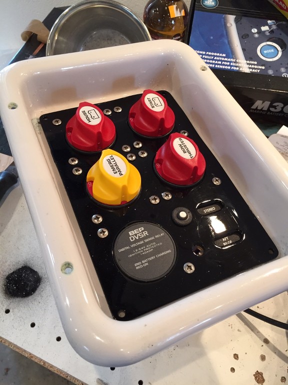
Now to finish the other project before 240V conversion...
That looks complex !
I took what I think is a simpler route.
Original VP 120A charge splitter on the bulkhead.
Charger fuses swapped for breakers and connected to the charge splitter rather than behind the switch panel.
Windlass battery to breaker connector cable changed from 35mm2 to 50 mm2; like the rest of that circuit.
Emergency systems to starter battery link changed from 12" long 35 mm2 to 5" long 50 mm2 ( still a bit small, the diesel engine boats have 70mm2 cables, but there's no room for a curved 70mm2 cable there )
A separate off-1-2-both battery switch panel on the starboard side for the system batteries. With the amplifier breaker connected to the systems batteries rather than the engine battery, plus the active corrosion protection fuse and bilge pumps fuse ( plus a LCD voltmeter/ battery selection switch). 70mm2 cable across the boat.
If anyone is considering doing some battery rewiring, I really do recommend buying a hydraulic crimper (around £30 in the UK , ca USD 45). You can easily make custom cables at a fraction of the cost of premade ones. I shortened all the battery cables, from the standard 72" or 108" to an appropriate length. The crimping on some of the originals was a bit suspect.
.............and as for the 14 pin connector, well there are none shown on the wiring diagram that came with the boat ( dated 2007). They clearly upgraded the connectors ( to an "almost" waterproof type) and changed the wiring compared to earlier ones, but no schematics are available even to dealers.
EDIT: I understand it was a grim time for FW employees in 2008/9 ( it was a bad time for me as well !). In the paperwork for the boat there was a copy of an E-mail from FW HR to employees saying what they should do if redundancy was initiated, Horrible. Since then though FW should have been more responsive to their dealers as far as wiring info is concerned.